Welcome to No Limit Sound Productions

Company Founded
2005
Overview

Our services include Sound Engineering, Audio Post-Production, System Upgrades and Equipment Consulting.
Mission
Our mission is to provide excellent quality and service to our customers. We do customized service.

Monday, November 11, 2019

Q. How do I create a stereo mix from mono material?

By Hugh Robjohns
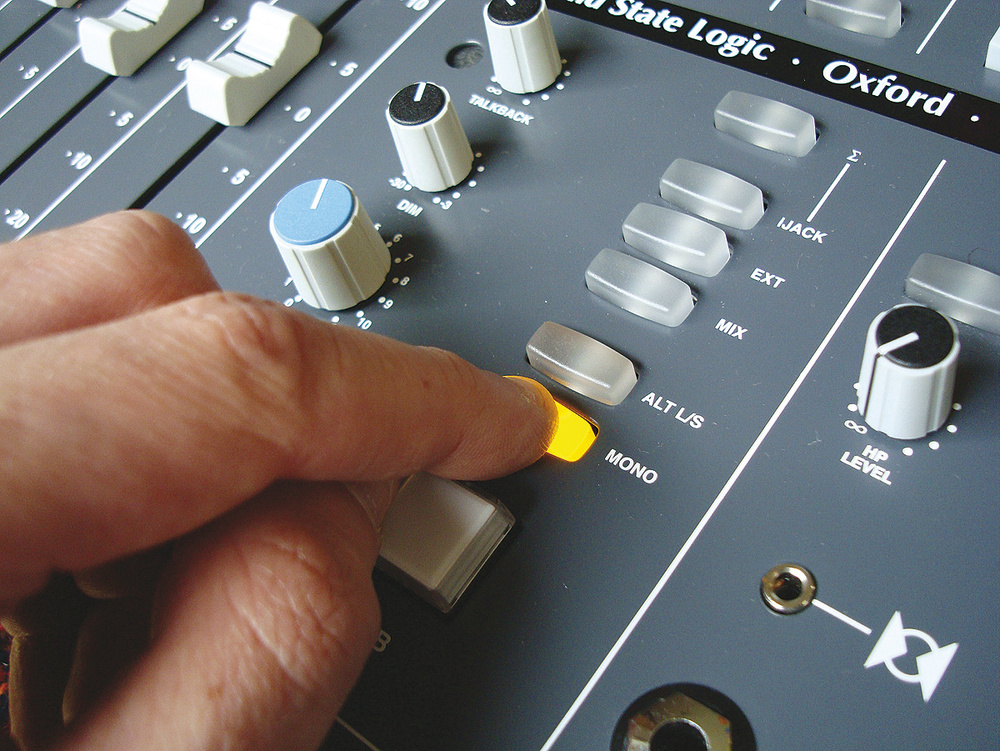
Finger on Mono button of console.
I want to remix some old mono tracks in stereo. Can you offer any advice or suggest any tricks to achieve this?

Jon Bennet

Technical Editor Hugh Robjohns replies: The first thing to accept is that you cannot create a true stereo (or surround) mix from mono material; you can only give an impression of greater width. In other words, there is nothing you can do to separate instruments and pan them to specific points in the stereo image, as you could if mixed originally for stereo.

One of the best ways to create fake stereo from mono is to make an M&S (Middle and Sides) stereo mix from the mono source. You'll need to treat the mono source as the 'M' element of an M&S stereo matrix, and decode accordingly, having created a fake 'S' component.

This fake 'S' signal is simply the original mono signal, high-pass filtered (to avoid the bass frequencies being offset to one side of the stereo image) and delayed by any amount between about 7ms and 100ms, according to taste. The longer the delay, the greater the perceived room size — but I would only recommend delays over about 20ms for orchestral or choral music.

Here's how to do it practically: take the mono signal and route it to both outputs on the mixer equally, or, in other words, pan it to the centre. Take an aux output of the mono signal and route it to a digital delay. Ideally, high-pass filter the signal before the delay. A 12dB-per-octave high-pass filter set at about 150Hz should do the job, but this figure isn't critical and will affect the subjective stereo effect, so experiment. Alternatively, high-pass filter the output from the delay.

You now need to derive two outputs from this delayed and filtered signal, which may be possible directly from the delay processor, if it's of the mono in, stereo out variety, for example, with the same delay dialled into both channels. If not, use a splitter cable or parallel strip in a patch bay to produce two outputs.

Route this pair of filtered and delayed signals back to the mixer, ideally into a stereo channel, or, if not, into two mono channels panned hard left and right. Invert the phase of one of the channels. If using adjacent mono channels, fix the faders together and match the input gains so that the gain is the same on both channels.

Now, with the original mono signal faded up, you should hear the central mono output, and if you gradually fade up the fake 'S' channels, you will perceive an increase in stereo width. The length of delay, the turnover frequency of the high-pass filter and the relative level of mono 'M' and fake 'S' channels will determine the perceived stereo width.

If you overdo the amount of 'S' relative to 'M', then you will generate an ultra-wide stereo effect, and if monitored through a Dolby Pro Logic decoder, this will cause a lot of the signal to appear in the rear speakers.

The advantage of this fake stereo technique is that if you subsequently hit the mono button, the fake 'S' signal cancels itself out and disappears completely, to leave the original mono signal unaffected.


Published December 2003

Friday, November 8, 2019

Q. How can I attach acoustic foam to the wall?

By Chris Korff
Gluing acoustic foam to walls can be impractical, which is why Paul White hit on the idea of gluing old CDs to the foam and using those to hang the foam on nails or hooks. The dog is, reportedly, not essential to the process...Gluing acoustic foam to walls can be impractical, which is why Paul White hit on the idea of gluing old CDs to the foam and using those to hang the foam on nails or hooks. The dog is, reportedly, not essential to the process...
I have bought some Auralex LENRD bass traps and I wondered if anyone at SOS has had any success fixing them to a soundproof plasterboard wall/ceiling without them dropping off in a matter of minutes! Any help would be much appreciated.

Ray Parkes

SOS Reviews Editor Chris Korff replies: Auralex sell their own brand of spray-on adhesive (there may be a cheaper alternative, but I'm afraid I can't remember what type of glue it is!), and as you'd expect it works very well. But depending on where you want to fix the foam it might actually work rather too well; you won't be able to peel the foam off the walls again without destroying the foam and the paintwork!

Our very own Editor In Chief Paul White came up with an ingenious solution that he's used in a number of our Studio SOS visits: he uses the adhesive to attach old CDs to the foam, and then uses the holes in the centre of the CDs to hang the foam on nails or hooks, just as you would with a picture frame. That way you can always move the foam to another location if needed.


Published November 2019

Wednesday, November 6, 2019

Q. Why does 'Class' matter in an amplifier?

By Hugh Robjohns
I saw a mic preamp advertised as 'Class A' and 'Transformerless.' What do these terms mean and why exactly are they a good thing?

SOS Forum Post

Technical Editor Hugh Robjohns replies: The 'class' of an amplifier refers to the circuit topology used, and is independent of whether the circuit uses valves, transistors or FET as the active devices. 
Buzz Audio MA2.2 preamp.In a Class-A circuit the output device is arranged to pass the entire audio waveform — both the upper and lower halves of the signal waveform. This provides the cleanest, most transparent sound, but the necessary biasing arrangements makes this kind of circuit power-hungry, and it tends to generate a lot of heat as a result. 
Focusrite ISA220 features Class-A circuitry.

A more efficient circuit design is the Class B, which uses two output devices, one to handle only the upper portion of the sound waveform and another to handle the lower half. The benefit is that only one device is working at any time, and when there is no input, both are switched off, allowing huge savings in power consumption and heat generation. The drawback is that at the zero crossover point between the positive and negative halves of the waveform, one device might have switched off before the other has come on, and that results in 'crossover distortion' — which isn't a good thing in high-quality audio circuits.
The Buzz Audio MA2.2 (top), Focusrite ISA220 (middle) and TL Audio VP1 (above) all feature Class A circuitry, sacrificing efficiency for superior sound quality.The Buzz Audio MA2.2 (top), Focusrite ISA220 (middle) and TL Audio VP1 (above) all feature Class A circuitry, sacrificing efficiency for superior sound quality.

The compromise solution is a combination of both topologies (Class A and Class B), and it's called... Class AB. This also employs separate devices to handle the upper and lower portions of the sound waveform, but they are biased in such a way that both are operating when the signal is close to the zero crossover region, and thus crossover distortion is much less of a problem.

These basic circuit topologies can be employed in any amplifier design, whether it's a power amplifier to drive loudspeakers, a microphone preamplifier, or a line driving amplifier, as well as in discrete-component or integrated (IC) circuits. However, Class A remains the best choice for audio systems where the power consumption can be tolerated. 

The term 'transformerless' refers to the absence of a transformer within the circuit. Transformers can be useful things in audio systems, providing 'galvanic' isolation between circuits and systems, or impedance-matching and the balancing (or unbalancing) of audio circuits, or even providing a 'free' voltage gain, depending on the application. However, transformers also have disadvantages, such as large size and weight in audio applications, and the introduction of large phase shifts which can become audible under some circumstances and therefore undesirable. 

Many modern electronic circuits have been developed to replicate some of the desirable characteristics of transformers, without their associated disadvantages, and this is often championed as an overall advantage. Hence the 'transformerless' term is generally seen as a good thing, along with Class A. However, there are some circumstances where transformers still provide the best solution, and the inherent sonic qualities are often deliberately sought.


Published October 2003

Monday, November 4, 2019

Q. How do audio and video stay in sync?

By Hugh Robjohns
Video and audio sync.
I'm having some problems understanding exactly how audio-to-video synchronisation works. I know that the clock generates a pulse — it gives off a voltage at a certain frequency. But how does this keep the sound and the pictures in time?

SOS Forum post

Technical Editor Hugh Robjohns replies: The pulses generated by the clock generator are just that — pulses — but at a very precisely controlled rate. These are intended only to control the rate at which pictures or audio samples are taken, or the speed at which an analogue tape is dragged past the recording heads.

The missing link that provides the positional information is the timecode generator, and all this does is count the pulses from some arbitrarily agreed starting point, and keep track of that count as timecode within the recording medium somewhere.

When replaying, the replay clock generator provides more pulses to determine the replay speed of the medium, and the timecode numbers identify which bit of sound is supposed to align to which pictures.
Let's consider the example of pictures on a video tape, and sound on a separate digital recorder of some sort, imagining that you want to replay both together in perfect sync.

The 'rules' for this kind of material are that there must be 25 picture frames every second (sticking with European standards here for simplicity — the US ones are different) and 1920 audio samples every second (for the standard 48kHz sample rate), and that the first of each batch of samples must align precisely with the start of each picture frame. This last point is to facilitate editing, so that when cutting on a picture boundary you don't end up cutting halfway through an audio sample!

To maintain these rules when recording, both the video camera and the digital sound recorder have to be running at the same very precisely controlled rate, and this is provided by something called a 'sync pulse generator' or SPG. It provides a continuous series of very precise pulses at the rate(s) required by the equipment to ensure that they capture 25 picture frames and sample 1920 audio samples every second.

In a studio setting, there will be one SPG which originates all the required timing pulses which are then distributed as required. On location, this is a little impractical as it is often desirable to have camera and sound moving independently of each other, so sync cables connecting the two back to a central SPG is not a great idea. In this case, the usual solution is to equip the camera and the sound recorder with their own internal SPG systems, and to synchronise these to each other at regular intervals. Crystal oscillators are extremely stable these days and once matched to each other, they will drift relative to each other very slowly indeed. Provided they are re-sync'ed every couple of hours (usually whenever changing batteries or tapes, in practice) they will remain sufficiently close to each other's timing to be fixed together.

So that takes care of the rate at which pictures and sound are captured. The next step is to make sure that if separated, the pictures can subsequently be linked to the correct sound. This is achieved by using timecode. Timecode is simply a series of numbers (generally in the time format of hours, minutes, seconds and frames, but it could just as easily be a continuous stream of consecutive numbers. The timecode simply counts the SPG pulses in order to allocate each picture frame (or each block of 1920 audio samples) with a unique number from which it can later be identified.

When the camera and sound SPGs are synchronised to run at the same rate, their associated timecode generators are also synchronised so that they start counting picture frames (or blocks of 1920 samples) from the same point. After that, the camera and sound recorder can do their own thing, safe in the knowledge that the rate at which the picture frames are being shot, and sound samples are being captured are identical, and that each is being identified with the same timecode number sequence.

It is worth noting that the pulses and counting have to continue whether the recorders are actually recording anything or not. In practice, and purely for convenience the timecode numbers are usually aligned to the actual time of day (TOD) when working in this mode, and hence this is often called 'TOD working'. Obviously, this practice will result in discontinous timecode sequencing on the recorded tape as the recordings are started and stopped throughout the shooting day. Most editing controllers or workstations don't like that much, so it is usual to record for at least 10 seconds before the wanted material to make editing easier (although it is not disastrous if this can't be achieved).
In post-production, when it comes to putting the pictures and sound together, the rate at which the pictures are reproduced will be controlled by the pulses from the studio's SPG. The same SPG will also provide suitable pulses to control the rate at which the digital sound system produces audio samples — so we know that pictures and sound are being replayed at exactly the same rate that they were filmed at.

Now we just need to make sure they both start at the appropriate place, and this is where the timecode comes in. A suitable start point will be identified on the video source and the corresponding timecode noted. The sound system will then search for the same timecode number within its recordings and position itself accordingly. When the picture and sound replay is started, the speed of the two sources is controlled by the SPG, and the system will 'nudge' one of them (usually the sound, but not always) backwards or forwards slightly until the timecode information aligns precisely. Once aligned, the only thing controlling the speed is the pulses from the SPG.

In the case of video equipment, the required pulses from the SPG are provided in the form of a composite combination of pulses called 'video B&B' (Black and Burst) or 'Colour Black'. This signal contains the vertical sync pulses that define the start and end of each picture frame, the horizontal sync pulses to define the start and end of each picture line, and the colour subcarrier which is used to make sure the colour information is coded correctly. In the case of digital audio equipment, the required pulses from the SPG are usually simple pulses at the sample rate — a signal called 'word clock'. Some systems will also use the AES or even S/PDIF composite signal, which embeds the word-clock information with the audio data.

Some video SPGs can also generate digital word clocks directly. In most cases, though, a B&B signal from the sync pulse generator has to be used as a reference to a digital clock generator, which then generates suitable digital word clocks for the digital equipment, locked to the video sync pulse generator.


Published October 2003