Wednesday, August 31, 2016
Tuesday, August 30, 2016
Q. Why do my mixes clip when I apply a high-pass filter?
By Sam Inglis

Here we see the characteristic 'hump' just above the turnover frequency of a shelving filter.
There's something happening when I master my mixes that I can't find an explanation for. This has been bothering me for nearly two years, so I thought it was time to call the experts! After maximising my mix, so that the level of the audio is just below the point of clipping, if I insert a high-pass filter at, say, 40Hz, suddenly the audio starts to clip. I thought that after inserting a high-pass filter the level should drop, but this is not the case. I've tried it with several EQs but always with the same result. What is happening? I've been using digital EQ, but will this still happen with analogue EQ?
Johan De Visser
Features Editor Sam Inglis replies: It's surprising, but true, that using EQ can cause clipping whether you are cutting or boosting. There are two reasons for this.
One is that EQ changes the phase relationships between the different frequencies that make up a complex signal, such as a full mix. The result of this is that even though you're cutting the low frequencies, you could be shifting other frequencies around in such a way that they reinforce one another at a point where they had not previously done so. It's also possible that whatever signal element you removed was actually serving to 'cancel out' another element at some points, so removing it has created larger peaks at these points.
The other reason is that some EQ designs actually have a resonant peak at the corner frequency. If this is the case then applying a low-pass filter at, say, 40Hz might actually introduce more energy than it removes, assuming there was nothing below 40Hz in the signal to start with.
It's possible to experience gain increases when cutting with both analogue and digital EQ — it's in the nature of equalisation that this will happen. The answer is to always do loudness maximising as the last process in the mastering chain (apart from dithering) — always use EQ before the maximiser, not after.
0
Published December 2005
Monday, August 29, 2016
Saturday, August 27, 2016
Q. Is there something wrong with my vintage spring reverb?
By Steve Howell
I have just bought an old spring reverb unit called the Great British Spring off eBay. It sounds great but if I feed any drums through it, or a percussive synth sound, it makes a weird 'ping' sound. I've had a look around the Internet and can't find much if any info on the thing. Can you help?
Rob Pope
SOS contributor Steve Howell replies: The Great British Spring was very popular in the '80s — I had one myself. One of the first affordable, decent-quality spring reverbs, it arrived at a time when Fostex were bringing fairly serious eight-track reel-to-reels to the market — it was a marriage made in heaven for the emerging home studio market. That said, the GBS was of serious enough quality to have been adopted in 'proper' studios as a cost-effective way to add extra reverb channels to supplement the main plate reverb.
Spring reverbs work by feeding the input signal, typically from an effects/aux send, to a transducer that 'excites' one or more of the springs. The signal travels down the spring and is picked up by another transducer at the other end, then sent to the output and on to the effects return. But it's not quite as simple as that, as the signal also 'bounces' back along the spring, colliding with other signals on their way down and causing complex pseudo-reflections. We perceive this as a reverb effect, and the more springs a unit has, the more diffuse the reverb effect is.
The length of the spring dictates the reverb length and density — the GBS's springs are quite long and give a nice hall reverb effect. However, as with all spring reverbs, percussive attack transients can cause the springs to become temporarily unstable, generating all sorts of unpleasant audio artifacts, as you've found out.
The simplest solution is just to reduce the level of the signal going to the GBS. This will prevent the springs from getting over-stimulated and thus will eliminate (or at least reduce) the 'ping' effect. The down side to this is that to have the same level of reverb on the sound, you will have to increase the reverb return level which will, of course, increase the amount of noise — these electro-mechanical devices are not known for their noise-free operation! However, even that can be overcome. You see, the frequency range of the springs is limited so, by bringing the reverb returns back through channels that have EQ, you can roll off the top end to reduce the hiss coming from the unit without adversely affecting the reverb sound too drastically, if at all. In fact, given the simplicity of the GBS (and spring returns in general), using EQ can add a lot of creative as well as correctional possibilities.
A more elaborate solution is to run the effects/aux send that is feeding the GBS via a limiter set pretty hard, so that the signal never reaches the level that will cause the springs to become unstable. Many more expensive spring reverbs had just such a facility built in.
Published December 2005
Friday, August 26, 2016
Thursday, August 25, 2016
Q. What factors affect the quality of a microphone capsule?
By Hugh Robjohns
I am curious to know more about the design and construction of capacitor mic capsules. For example, what is it about the capsule or the way it is mounted that dictates the polar pattern of the mic? If the capsule is sturdy and made from good-quality parts, what other factors come into play which affect its sound quality? Do capsule designs really differ that much from mic to mic?
Paul Curtis
Besides the capsule itself, the design and construction of the mic body and internal electronics also shape the sound of the mic.
Technical Editor Hugh Robjohns replies: A capacitor mic capsule is an extremely complex thing, and the very best are expensive and time-consuming to make.
 There are two basic types of capsule, working according to two different principles — pressure-operated and velocity-operated (also known as pressure-gradient). The former is constructed a bit like a snare drum — the capsule is, in essence, a sealed box with a diaphragm stretched across one side. The diaphragm acts like a pressure sensor, comparing the pressure changes caused by passing sound waves with the static internal pressure inside the box. The result is an omni-directional polar response —the direction of the sound waves don't matter, the diaphragm is only sensitive to the fact that they pass by.
The other way of doing things is to suspend the diaphragm in free space so that sound waves can get to both sides. In this case, the diaphragm moves (hence 'velocity') as a result of the pressure difference (pressure gradient) between the two sides. This arrangement gives a figure-of-eight response — the capsule is sensitive to sounds from front and back, but insensitive to sounds from the sides.
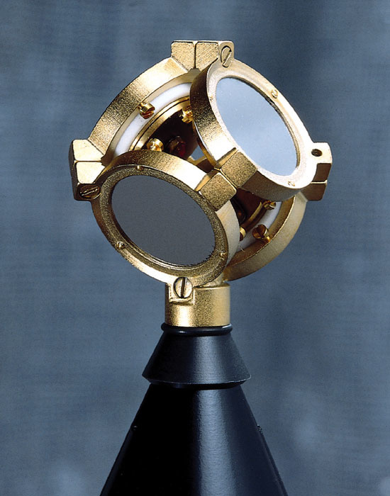
Often, it is more useful to have a mic that is sensitive to frontal sounds but rejects rearward ones — the familiar cardioid polar pattern. A cardioid pickup pattern is produced by combining equal proportions of pressure operation and pressure-gradient operation, and the earliest cardioid mics actually did have both an omni and figure-of-eight capsule side by side in the same box, with their outputs summed together before reaching the output terminals.
As Paul White discovered when he visited the Rode Microphones factory (see SOS August 2005), the utmost precision is required for drilling holes in a cardioid mic's backplate.
, the utmost precision is required for drilling holes in a cardioid mic's backplate.")
These days, most cardioids are 'phase shift' or 'labyrinth' designs which are constructed with a single diaphragm, like a pressure-operated mic (the snare drum), but with special convoluted passageways in the rear plate which allow sound to find its way through to the inside of the diaphragm after a time delay. The way this works is rather less obvious than the two prime capsule designs, and would take more space to explain than I have available here, but you can learn more about the subject by reading this article from SOS September 2000: www.soundonsound.com/sos/sep00/articles/direction.htm.
In terms of construction, there are literally dozens of different parameters to consider. There's the material the diaphragm is made from and its shape, thickness and tension, there's the spacing between the diaphragm and the back plate, the damping arrangement, the isolation dielectrics, the polarising voltage and so on and so on.
In the case of a cardioid capsule, there is also the complex arrangement of the rear chamber labyrinth to consider, and how that affects the polar pattern and the linearity of the capsule's off-axis frequency response. Entire books have been written on this subject alone!
Then, once the capsule has been designed and built, it has to be mounted in a mic body, the size and shape of which (along with the grille) affects the response of the capsule. And then there is the impedance converter circuitry, the powering circuitry and the output circuitry to consider, all of which affect the sound of the mic further.
This is why it is relatively easy for manufacturers in the Far East to reverse-engineer established mics and build copies very cheaply. But it is extremely hard for them to design new models from the ground up because the real science involved is known by a relatively small group of people.
I am curious to know more about the design and construction of capacitor mic capsules. For example, what is it about the capsule or the way it is mounted that dictates the polar pattern of the mic? If the capsule is sturdy and made from good-quality parts, what other factors come into play which affect its sound quality? Do capsule designs really differ that much from mic to mic?
Paul Curtis
Besides the capsule itself, the design and construction of the mic body and internal electronics also shape the sound of the mic.
Technical Editor Hugh Robjohns replies: A capacitor mic capsule is an extremely complex thing, and the very best are expensive and time-consuming to make.
 There are two basic types of capsule, working according to two different principles — pressure-operated and velocity-operated (also known as pressure-gradient). The former is constructed a bit like a snare drum — the capsule is, in essence, a sealed box with a diaphragm stretched across one side. The diaphragm acts like a pressure sensor, comparing the pressure changes caused by passing sound waves with the static internal pressure inside the box. The result is an omni-directional polar response —the direction of the sound waves don't matter, the diaphragm is only sensitive to the fact that they pass by.
The other way of doing things is to suspend the diaphragm in free space so that sound waves can get to both sides. In this case, the diaphragm moves (hence 'velocity') as a result of the pressure difference (pressure gradient) between the two sides. This arrangement gives a figure-of-eight response — the capsule is sensitive to sounds from front and back, but insensitive to sounds from the sides.
Often, it is more useful to have a mic that is sensitive to frontal sounds but rejects rearward ones — the familiar cardioid polar pattern. A cardioid pickup pattern is produced by combining equal proportions of pressure operation and pressure-gradient operation, and the earliest cardioid mics actually did have both an omni and figure-of-eight capsule side by side in the same box, with their outputs summed together before reaching the output terminals.
As Paul White discovered when he visited the Rode Microphones factory (see SOS August 2005), the utmost precision is required for drilling holes in a cardioid mic's backplate.
, the utmost precision is required for drilling holes in a cardioid mic's backplate.")
These days, most cardioids are 'phase shift' or 'labyrinth' designs which are constructed with a single diaphragm, like a pressure-operated mic (the snare drum), but with special convoluted passageways in the rear plate which allow sound to find its way through to the inside of the diaphragm after a time delay. The way this works is rather less obvious than the two prime capsule designs, and would take more space to explain than I have available here, but you can learn more about the subject by reading this article from SOS September 2000: www.soundonsound.com/sos/sep00/articles/direction.htm.
In terms of construction, there are literally dozens of different parameters to consider. There's the material the diaphragm is made from and its shape, thickness and tension, there's the spacing between the diaphragm and the back plate, the damping arrangement, the isolation dielectrics, the polarising voltage and so on and so on.
In the case of a cardioid capsule, there is also the complex arrangement of the rear chamber labyrinth to consider, and how that affects the polar pattern and the linearity of the capsule's off-axis frequency response. Entire books have been written on this subject alone!
Then, once the capsule has been designed and built, it has to be mounted in a mic body, the size and shape of which (along with the grille) affects the response of the capsule. And then there is the impedance converter circuitry, the powering circuitry and the output circuitry to consider, all of which affect the sound of the mic further.
This is why it is relatively easy for manufacturers in the Far East to reverse-engineer established mics and build copies very cheaply. But it is extremely hard for them to design new models from the ground up because the real science involved is known by a relatively small group of people.
Published December 2005
Wednesday, August 24, 2016
Q. Is it possible to record in surround on only two tracks?
 and a coincident omnidirectional mic (blue) can be combined to produce a directional cardioid pickup pattern (green). Flipping the polarity of the omni reverses the direction of the cardioid pickup.")
This simplified polar pattern diagram shows how a figure-of-eight mic (red) and a coincident omnidirectional mic (blue) can be combined to produce a directional cardioid pickup pattern (green). Flipping the polarity of the omni reverses the direction of the cardioid pickup.
Would it be possible to use two figure-of-eight mics to create a surround sound recording on a two-track recorder, which could be decoded and mixed later on? The two mics would be placed at 90 degrees capturing left and right and front and back respectively. I'm after a quick and portable way to make surround recordings in the field, and portable recorders with more than two inputs are expensive! As far as I can see this could work, unless there's something I'm missing about figure-of-eight decoding?
SOS Forum Post
Technical Editor Hugh Robjohns replies:
There is something you are missing — a third mic to resolve the ambiguity inherent in a figure-of-eight mic over which side of the diaphgram the sound strikes. You cannot derive front-to-back directional information with just two crossed figure-of-eight mics.
Imagine I'm in a studio and you are in a control room, without sight lines between the two. There is a single figure-of-eight mic in the studio and I'm talking into it. How could you tell whether I was talking into the front or back of the mic just by listening? The answer is that you couldn't — a figure-of-eight mic provides signals of identical level from front and rear sources. Yes, the polarity of the signal is inverted between front and rear sources, but without a reference to know which polarity was which, you are no better off.
If you think about it, when you combine the two coincident figure-of-eight mics mounted at 90 degrees, you effectively end up with another 'virtual' figure-of-eight pointing midway between the two original mics. You can use that to provide left-right discrimination — which allows the arrangement to be used for stereo — but you will get the same level of output from a source behind and to the right of the array as you would from one to the left front. That doesn't matter in stereo: in fact it is often very useful that rearward sounds are folded back onto the front. However, it is obviously a problem in surround because we need to be able to have rearward sounds coming out of the rear speakers!
So, what we need to be able to do is create virtual polar patterns that have front-back discrimination, and that basically means creating 'virtual' cardioid patterns. These can be derived by combining an omnidirectional mic's polar response with a figure-of-eight.
If you have two coincident figure-of-eights, facing left/right and front/back, and you add to that a coincident omnidirectional mic, you can combine them in various ways to create virtual cardioid patterns pointing in almost any direction you like. Let me explain how...
Consider what happens if you mix together the output of an omnidirectional mic and figure-of-eight, the two capsules being coincident. The omni mic picks up sound from all directions equally. The figure-of-eight picks up sound only from the front and back, rejecting sound sources to the sides, and its rearward pickup is in the opposite polarity to the front.
If we arrange the polarity of the omni to be the same as the front of the figure-of-eight mic, then when you mix the two mic outputs together their contributions will add together for frontal sound sources. So the resulting 'virtual mic' will be very sensitive to frontal sound sources.
Sources to the side are not picked up at all by the figure-of-eight mic, but the omni still hears them. So the 'virtual mic' created by the combination of the two is not as sensitive to sounds from the sides as it was from the front, but it does still hear them.
 and one omni-directional capsule (W), courtesy of Soundfield.") The
four coincident capsules of a B-format Soundfield mic, and a diagram
showing the intersecting pickup patterns of the three figure-of-eight
capsules (X, Y and Z) and one omni-directional capsule (W), courtesy of
Soundfield.
The
four coincident capsules of a B-format Soundfield mic, and a diagram
showing the intersecting pickup patterns of the three figure-of-eight
capsules (X, Y and Z) and one omni-directional capsule (W), courtesy of
Soundfield.Sources to the rear are heard by both the figure-of-eight and omni, but the figure-of-eight's output is of the opposite polarity to the omni. Hence, when the two outputs are combined they will cancel each other out. Thus the virtual mic hears nothing at all from the rear, and if you draw this polar pattern out accurately you'll discover that we have just created a cardioid microphone (facing forwards). You can also create other first-order polar patterns (sub-cardioid, hypercardioid and so on) by varying the ratio of the omni and figure-of-eight contibutions (in other words changing the gain of each).
So you see that by introducing an omni mic into the array, you can resolve the inherent front/rear ambiguity of the figure-of-eight pickup patterns, by converting them into cardioid patterns, and by adjusting the ratios and polarities of the signals from the two figure-of-eights, you can make those cardioids face in pretty much any direction you like. You can now generate any number of virtual microphone outputs which 'hear' only the sources in front of them — front left, centre front, front right, rear left and rear right, for example.
This is the basis of horizontal Ambisonic encoding — the 'B-format' — as used by the Soundfield mic. The omni component is called W, the front/back figure-eight is called X and the left-right figure-eight is called Y. The Soundfield mic also adds a third figure-eight element for the up/down axis (called Z), although this isn't really needed in most surround applications. You can read more about the Ambisonic approach in SOS October 2001.
Another (arguably more practical) way of recording horizontal surround sound is the MSM format. This uses the same basic concepts, but is constructed from a pair of matched cardioids facing to the front and rear, plus a sideways-facing figure-of-eight. Again, all three should be coincident. The front cardioid and the sideways figure-of-eight are decoded as a conventional M&S pair for the frontal sound stage, while the rear cardioid and the same figure-of-eight are decoded as another M&S pair for the rear channels.
However, whether you adopt the crossed figure-of-eights plus omni approach (WXY format), or the front/rear cardioids plus figure-of-eight approach (MSM format) you do need to be able to record at least three channels, and there is no getting away from that!
If you really want to encode surround onto a two-track machine, you have to use some form of phase/amplitude matrix system like Dolby Pro Logic or RSP Circle Surround. However, while these formats are acceptable for final mixes delivered to the end user, they are far too restrictive for source recordings because you can't easily manipulate the signals to alter the spatial surround characteristics later on, as you can with either of the three-channel surround recording techniques described above.
Published December 2005
Tuesday, August 23, 2016
Monday, August 22, 2016
Power & Electrical Safety On Stage

Staying safe on stage is more than a matter of simply making sure that willing hands are available before taking a dive. Knowing how to properly handle the mains power we all need is also crucial to performance health...
Whatever the size, complexity or cost of your live sound rig, one of the first — if not the first — question on your mind when you get to a venue will usually be "where do I plug it in?" Depending on the venue, the answer can vary from a wall-socket behind a plant pot to a dedicated and professionally-installed supply that is reserved for your exclusive use, fully tested and certificated, and for which (with any luck) you'll have brought an appropriate connector. Whatever you encounter, you'll need to know some basic rules. When it comes to portable live-sound systems, this means firstly, using a suitable electrical supply; secondly, using suitable equipment; and, thirdly, connecting and using that equipment safely.

How much power will the average band's gear actually need? The only way to know for sure is to add up the power requirements of each individual item.Photo: Mike Crofts
How Much Mains Power?
What constitutes a suitable supply will depend, of course, on what you need to plug into it: if it's your own equipment you'll presumably know what supply capacity is required, but there may be other factors to consider if additional gear needs to be connected to the same supply. Such gear might include a visiting disco, a lighting rig, or other event equipment — for example, fridges at summer events.A good first step, then, is working out what current your equipment will draw from the mains. The power rating of each piece of gear should be stated on a panel fixed close to the mains connector, or where a fixed mains lead enters the equipment. The power rating may be expressed as a current (in Amps) or as a power figure in Watts. It's generally best to work out the total current your gear will draw, adding up all the individual figures to find the total load you'll be connecting to the mains. To convert Watts to Amps, divide the Wattage figure by 230 (mains voltage). As an example, a piece of equipment with a mains power rating of 100 Watts (not 100W of audio power) will draw a little under half an Amp. In a small venue that is only offering 13-Amp sockets of the normal domestic type, you can then work out how you need to wire up. If the total connected load of your system — including the backline equipment — is comfortably within the rating of a single or double 13-Amp socket, it's perfectly alright to connect it all from a single point. After all, that's what they're designed for! Try to avoid too many connections between this point and your equipment. It's much better to have a single power lead of the required length than two shorter ones joined together: less to go wrong!

A professionally made distribution box with meters to indicate AC mains voltage and current.Photo: Mike Crofts
Working It Out
One common mistake is assuming that audio output power is the same as the mains power required to operate the gear. If an amplifier were 100 percent efficient, you could, in theory, use all the mains power as audio output power, but this is not the case in practice, as some of the power used by the amplifier is dissipated as heat. A typical full-range 'active' speaker with built-in amp modules, rated at 240 Watts audio output, would have a mains power rating somewhere around 350 Watts. A useful rule of thumb (if you don't have the manufacturer's stated figures) is to multiply the audio output power by 1.4 to get an idea of how much mains power would be needed, then divide by 230 to find out the current consumption.The table below gives a rough guide to the supply current likely to be required by a band with three backline amps and a vocal PA (based on UK voltage). Bear in mind that equipment may demand a much bigger supply current when it is first switched on, so don't be tempted to turn everything on from a single switched socket — you wouldn't want to do this anyway, for many other reasons, such as risking a huge pop through your speakers! Also consider that the power that you can safely run your system on may not be enough to realise its full performance capability. Any system capable of delivering good bass power will need to draw a hefty current from the mains, and if, in the above example, we were to replace our typical small speakers with, say, a pair of Mackie SA1521s, the makers recommend that each speaker's mains supply is capable of providing seven Amps at 230 Volts! This is, of course, not a constant current requirement, but it does illustrate how important a good power source is for getting the best from your gear.
Equipment | Mains Power needed | Mains Current needed | Amps |
| 2 x 240W active PA speakers | 480W x 1.4 = 672W | 672 / 230 = 2.92 Amps | 2.92 |
| Mixer | 100W (stated) | 100 / 230 = 0.44 Amps | 0.44 |
| 2 x rack processors | 20W each (stated) = 40W | 40 / 230 = 0.17 Amps | 0.17 |
| 3 x 100W backline amps | 300W audio x 1.4 = 420W | 420 / 230 = 1.83 Amps | 1.83 |
| TOTAL = | 5.36 | ||
| ROUNDED UP = | 5.5 Amps |
User Beware
While we're talking in Amperes, it's worth remembering that electrical current is a dangerous animal; a current of only 50 Milliamps (0.005 Amps) can be fatal, and our typical small rig above is using over a thousand times more current than this. Safety is thus a huge consideration, and the use of a suitably rated supply is only the beginning. The best way to stay safe is to use only well-maintained equipment (including cables and connectors) that are properly designed for the task in hand, and to make sure that they are used as the manufacturers intended.
A professionally made distribution box with four 16-Amp outputs, all RCD protected, for limited outdoor use.Photo: Mike Crofts
If the venue in question is unfamiliar to you and you are responsible for providing and operating the PA, always check that the supply you're asked to use is suitable. Just because it's a 13-Amp socket doesn't mean that it's capable of supplying 13 Amps: it may have been DIY-installed as a spur from a domestic ring main, originally to light a garden shed or run a fountain or something! If you're operating in any kind of business or commercial premises, they should have an up-to-date electrical safety certificate. A quick look at the distribution board or consumer unit should show the overall current rating of the circuit you'll be using, and you can also see if it uses old-style wired fuses or the more modern MCBs (Miniature Circuit Breakers), which react more quickly if the rated current is exceeded.
Fuses and MCBs do not protect you from electric shock, so always make sure that your system is fed via a residual current device (RCD). This could be at the main board/box, on the socket itself, or at the point where a separate spur is fed. If you're not sure that this is the case, use your own RCD, either as a plug type or one of the RCD plug-in adaptors readily available for a few quid from any electrical retailer. The RCD should be as far 'upstream' as possible so that it protects as much as possible, and wherever it is, make sure you test it before use, by using the built-in test button. If it doesn't seem to work, find another!
A final word on RCDs: they are there as a backup in case anything goes wrong, not as a substitute for poorly-maintained, faulty or unsuitable equipment.
Going Through A Phase
Most small venues are likely to have a single-phase supply, as will normal domestic premises, and for the purposes of this basic article we won't be looking at the whys and wherefores of 'three-phase' systems, other than to point out that all the sound equipment should be connected to the same phase. Any other electrical equipment, such as lighting, should also share the sound-system phase if it is possible for a person to come into physical contact with both systems — for example, to touch the lights and a guitar at the same time. It's a given that the venue's technical staff should supervise any connection to a three-phase supply.Distribution Deal

A damaged mains plug recently discovered at the bottom of the cable trunk — to be disposed of straight away!Photo: Mike CroftsHaving found a suitable supply point, you now have to feed it to all your equipment. For all gigs where a 'proper' supply is available, I use a professionally made portable distribution box, which has a single 32-Amp inlet and 32-Amp breaker, feeding four 16-Amp outlets, all via separate combined RCD/MCBs. Although, on the face of it, I've got four 16-Amp outlets, giving a total of 64 amps, I can only use 32 Amps overall, with each outlet limited to 16 Amps. I run my front-of-house speakers from two of these feeds, the monitors and desk from the third, and the stage backline from the fourth. This splits up the load and ensures that each feed is fully RCD protected. As mentioned earlier, it is always best to have an RCD as far upstream as possible, and I would ensure that my original 32-Amp source incorporated suitable protection if available.
For smaller indoor events, a single 13-Amp fused RCD plug feeding into a multi-way distribution board (four or six sockets) is fine, as the total current can't exceed the 13-Amp fuse rating in your RCD plug. From this distribution board you should try, where possible, to connect direct to equipment, or feed the equipment in logical groups. Normally, you can take the initial feed from a socket at the back of the stage and run all your backline straight from this, with one feed going off to the PA system. If you need to use more than one socket in a small venue, ensure that all your signal connections are balanced, and never, ever remove an earth connection to get rid of hum or noise. Also take care when using those 'flying saucer' extension reels. They are very useful and neat, but remember that their maximum current-carrying rating only applies when the cable is fully unwound.
Care & Maintenance
All leads, connectors and equipment should always be checked before use, even if this is a quick visual check for any obvious signs of damage. If it's your own gear, you'll know it's all correctly fused, but it's best to check if you're not sure. Cables should be undamaged along their entire length and plugs should be securely clamped on, with no inner conductors visible. Cables with moulded plugs are a common sight nowadays, but these plugs cannot ever be re-used, and if damaged or removed for any reason they must be thrown away — preferably after destroying them so that an unaware person can't find one and plug it in. If anything looks faulty, then it probably is. Remove it from service and make sure it can't be used again until it has been repaired and tested.All electrical equipment, including cables and connectors should be stored and used in dry conditions unless it is designed for outdoor wet weather use and carries an appropriate IP rating (for mains connectors this will usually mean industrial 'Ceeform' types — coloured blue — either rated IP44 (which is splashproof) or IP67 (which is waterproof).

Never be tempted to 'lift' the earth wire for any reason. If you find a plug like this one, with the earth disconnected, don't use it.Photo: Mike Crofts
Summing Up
We've covered the basics of finding a suitable supply and connecting the gear to it, but there are other things to consider when rigging. Cable runs need to be thought out to avoid or minimise trip hazards, and a generally neat cabling job will be much easier to troubleshoot than a spaghetti surprise. Don't forget the rule 'signal before mains'. Connect the power leads last and switch on after everything has been connected in the signal path (with the master levels down, of course). Turn on your power amps last of all, and switch them off first when powering down the system.In this article I've taken a very basic and superficial look at the power side of live sound. There's a lot of additional good advice to be found, and it's well worth taking a professional approach and discovering as much as you can. After all, if you were going to jump out of an aeroplane you would, presumably, want to know that your parachute was (a) of the correct type; (b) correctly installed on your person; and (c) recently tested! Electrical power is a serious business, so if in doubt, ask a qualified electrician. If you don't know one personally, someone you know will, or you can look one up in the phone book.
There are also plenty of useful pages on the Internet. The UK's Health and Safety Executive web site, for example, has a lot of relevant information and links to some very good guidance publications. Check out www.hse.gov.uk.
Safety Checks
Your visual examination, before connecting any equipment, every time you're about to use it, should include checks for:
 records kept. Some venues will not allow you to use anything which hasn't been properly tested. Get a quote from your local electrician for testing; it's not expensive and is well worth it for the peace of mind.")
All portable electrical equipment should be periodically tested for electrical safety, and 'PAT' (Portable Appliance Testing) records kept. Some venues will not allow you to use anything which hasn't been properly tested. Get a quote from your local electrician for testing; it's not expensive and is well worth it for the peace of mind.Photo: Mike Crofts
- Damage to cables or plugs, including cuts, cracks, abrasions, bent or missing pins.
- Previous repairs or modifications, including exposed or taped-up cable joins and unsuitable connectors.
- Exposed inner conductors where the cable enters the mains plug.
- Signs of damage to casing and covers.
- Obvious signs of previous problems; for example, signs of water, moisture or heat damage.
- All wires are firmly attached (screws nice and tight) to the correct terminals, with no bare wires showing.
- The cable outer sheath is firmly gripped by the cord grip.
- There is no debris or signs of damage internally.
- Additional testing of earth integrity and insulation.
- Test results recorded and appropriate labels attached to the equipment.
- Failed equipment identified for disposal or repair.
Saturday, August 20, 2016
Friday, August 19, 2016
Q. What is the difference between mono with one speaker and mono with two?
 I
read recently that when top engineers check their mixes in mono, they
don't just hit a mono switch, but instead route the mix through a single
speaker to hear it in true mono. What's the difference between the two?
I
read recently that when top engineers check their mixes in mono, they
don't just hit a mono switch, but instead route the mix through a single
speaker to hear it in true mono. What's the difference between the two? A single speaker in a sealed enclosure is the classic means of monitoring in mono.
SOS Forum Post
Technical Editor Hugh Robjohns replies:
It's important to check the derived mono signal from a stereo mix to ensure that nothing unexpected or unacceptable will be heard by anyone listening in mono, as could be the case in poor FM radio reception areas, on portable radios, in clubs, on the Internet and so on. Mono compatibility, as it's called, is very important for commercial releases — the artist, producer and record company want the record to sound as good as possible in these less-than-ideal circumstances.
In addition to simply checking the finished product, mixing in mono — or regularly switching the monitoring to mono while mixing — is very useful and a good habit to get into. Summing to mono removes any misleading phasing between the left and right signals that can make a stereo mix sound artificially 'big'.
The crucial difference between auditioning the summed mono signal on a single speaker, as compared to a 'phantom' mono image between two speakers, relates to the perceived balance of the bass end of the frequency spectrum. When you listen to a mono signal on two speakers, you hear a false or 'phantom' image which seems to float midway between the speakers, but because both speakers are contributing to the sound, the impression is of a slightly over-inflated level of bass. Listening to mono via one speaker — the way everyone else will hear it — reveals the material in its true form!
Checking the derived mono is always best done in the monitoring section of the mixer or with a dedicated monitor controller. Although a mono signal can be derived in the output sections of a mixer (real or virtual), this is potentially dangerous — if you should forget to cancel the mono mixing, you'll end up with a very mono final mix. It does happen, believe me! Sadly, very few monitor controllers outside of broadcast desks and related equipment provide facilities to check mono on a single speaker. Most provide a phantom mono image, which is fine for checking imaging accuracy and phasing issues, but no good for checking the mono balance.
Published November 2005
Published November 2005
Thursday, August 18, 2016
Wednesday, August 17, 2016
Tuesday, August 16, 2016
Q. What is the best way to mike up a clarinet?
By Hugh Robjohns

DPA clarinet mic.
I'm in need of some help and advice. I was working with a group at the weekend who have a wind player in their line-up. She alternates between flute and clarinet. I had no trouble miking up the flute, but when it came to the clarinet I just could not get a signal that would cut through the mix, despite using a second mic. The mics I was using were a JTS small-diaphragm condenser (cheap but usually effective) and a Shure SM58 pointed towards the bell of the instrument, but slightly off-axis. I have spoken to another engineer who has also worked with the group and he confirms that he also had problems with the clarinet. Any suggestions?
SOS Forum Post
Technical Editor Hugh Robjohns replies: The clarinet has the widest dynamic range of any orchestral instrument, so it's no wonder you had problems! First of all, don't try placing the microphone anywhere near the bell. Most of the sound of the clarinet comes from the unstopped finger holes, so if you focus on the bell you'll be missing 70 percent of the instrument's harmonic range. Instead, you need to place a mic where it can 'see' the entire body of the clarinet.
Try placing the small-diaphragm condenser mic about a foot away and aiming more or less at the lower hand position. You can experiment with the height, angle and distance of the mic until you find a balance you're happy with, but it may also be worth having a quiet word with the player to explain the problem, in order to extract a more appropriate performance in terms of dynamics and consistent positioning relative to the mic.
In a live situation, miking may be more difficult because of spill, feedback or over-exuberant performers, amongst other things. If so, you might find it easier to use a clip-on instrument mic. There are lots on the market that will hold a small mic in a reasonable position and keep it there regardless of the gyrations of the player.
Published November 2005
Monday, August 15, 2016
Saturday, August 13, 2016
Q. How can I make the most of a small studio space?
By Tom Flint

When space is limited, you need to think carefully about how to lay out your studio.
I'm just about to set up a studio in a room of my house and I was wondering if you have any tips on where to put everything. I have quite a few keyboards, sound and effects modules, guitars and a computer workstation, and I also record vocals, so I need to provide for all those things. The room I have is quite small and I know it'll never be perfect in terms of acoustics, but can you offer any advice on general layout?
Tony Mendelle
SOS contributor Tom Flint replies: If your workspace doesn't feel right, you'll probably find it difficult to commit yourself to doing any work. Get it right, on the other hand, and hopefully inspirational recordings will follow!
The way I see it, a typical home studio has three important spots where most of the activity takes place, which we'll call the engineering seat, the performance seat and the listening seat, and it's a good idea to start by thinking about where these might be best situated. The engineering seat is where you'll be when working at a computer, hardware multitracker or stand-alone sequencer. This is where the majority of editing, mixing and programming takes place, and is therefore somewhere you are likely to be for long periods of time. The performance seat is the place where music is created and played, perhaps using a workstation keyboard, a guitar or a simple MIDI controller. It can even be the same place as the engineer's seat if you use a desk with a sliding keyboard shelf. The last significant spot is the listening seat. Even the smallest studio needs one, in my opinion. It is where you can relax with a cup of tea, listen to your music and ponder. Without one, your studio will merely be a place of work and you'll be tempted to leave it whenever you feel jaded. Naturally, this position should be angled towards the studio's speakers, but you won't be doing any really critical listening from here so you needn't worry too much.
For efficient working you'll want to have the most frequently used bits of kit within reach from the key working positions. If, for example, you are using hardware multi-effects processors patched into the send/return loop of a workstation, you'll want to be able to easily reach the effects parameter controls during mixing. Many pro studios tend to have racks of gear under the desk, but I avoid this arrangement at all cost. If, like me, you find touching your toes a struggle, you'll be much more comfortable having everything up at eye level. Not only does this leave leg room below, it also makes the programming of effects units or rack synths a more appealing prospect, allowing you to get the most from your equipment without having to move from your playing or mixing position. The space under the desk need not be wasted though. I use mine to store boxes and unused bits of kit, and it is also home to my two guitar amps, which I don't need daily.
If you are recording your own vocals and use hardware preamps, it is also vitally important to have them close to hand when standing near the mic, so that adjustments can be made while singing. In my setup, for example, I have a 10U rack of gear seated on top of my desk so that all my effects and preamps are between three and five feet high, which is ideal for checking settings and making adjustments. If the preamps are feeding a multitracker or computer workstation, it is also useful to be able to see the input meters on the display screen from the vocal position, at least while levels are being established. Once again, if everything is to hand, excessive levels can be curbed by simply reaching for the preamp output level control. It's often possible to use footpedals to remotely adjust transport controls when performing, but it is well worth arranging things so that recording devices can be manually operated too.

A comfy chair or two can make your studio a much nicer place to be.
Having the right desk surface can make all the difference, and often the most effective option is to build your own so that it fits the room, your equipment and your own physical stature. I built my desktop at a height that allows me to comfortably play my master keyboard either when I'm standing up or when seated on a stool. In fact, I have everything, including my multitracker, placed on the same desk so that it can be operated from both positions. You'll save money by building your own desk, too. My desk, which is nine feet long and two feet deep, has a frame built from thick planed pine and an MDF top, and it probably cost less than £40 in materials.
Putting up some shelves will give you somewhere to put boxes of leads and adaptors, old copies of SOS and other general studio clutter. The side benefit is that by placing them carefully they can also be used as a crude, but often effective, form of acoustic treatment. You might also consider hanging your guitars on the wall to free up floor space and mounting monitors on wall brackets to free up the desk.
One of the most limiting factors governing your studio layout will be the interconnectivity of the gear. Every studio requires power, audio I/O and, in most cases, a network of MIDI connections. For mains power, I like to wire up my own plug-boards so that I can cut the cable to the required length and run it around the edge of the room, well away from doorways. In fact, it's a good idea to make sure that there aren't going to be any cables running in front of doorways, cupboards and so on, otherwise sooner or later they'll get hooked on a fast-moving foot and will do some damage to you or your equipment. Furthermore, a patchwork of wires makes vacuuming difficult. Being able to clean a studio effectively is an important consideration, because dust can seriously damage audio equipment such as mics or faders.
MIDI leads are best kept as short as possible, because the data stream doesn't include any error correction and errors become more likely the longer the cable is, so it's worth planning the MIDI layout early on. If MIDI Merge or Thru boxes are used in the system, these can be carefully placed to act as hubs for the network.
It's possible to buy both audio and MIDI leads in a variety of colours and this is well worth doing, because it makes it far easier to distinguish each cable from the rest. Otherwise it's a good idea to label each lead using stickers wrapped around either end. Labels can be used for mains plugs too.
Before building your studio, it's also worth remembering that bad posture and poor ergonomics can cause repetitive strain injury (RSI) and other uncomfortable conditions. For more on the subject, check out the feature SOS ran in the January 2002 issue (www.soundonsound.com/sos/Jan02/articles/studioergonomics.asp).
When space is limited, you need to think carefully about how to lay out your studio.
I'm just about to set up a studio in a room of my house and I was wondering if you have any tips on where to put everything. I have quite a few keyboards, sound and effects modules, guitars and a computer workstation, and I also record vocals, so I need to provide for all those things. The room I have is quite small and I know it'll never be perfect in terms of acoustics, but can you offer any advice on general layout?
Tony Mendelle
SOS contributor Tom Flint replies: If your workspace doesn't feel right, you'll probably find it difficult to commit yourself to doing any work. Get it right, on the other hand, and hopefully inspirational recordings will follow!
The way I see it, a typical home studio has three important spots where most of the activity takes place, which we'll call the engineering seat, the performance seat and the listening seat, and it's a good idea to start by thinking about where these might be best situated. The engineering seat is where you'll be when working at a computer, hardware multitracker or stand-alone sequencer. This is where the majority of editing, mixing and programming takes place, and is therefore somewhere you are likely to be for long periods of time. The performance seat is the place where music is created and played, perhaps using a workstation keyboard, a guitar or a simple MIDI controller. It can even be the same place as the engineer's seat if you use a desk with a sliding keyboard shelf. The last significant spot is the listening seat. Even the smallest studio needs one, in my opinion. It is where you can relax with a cup of tea, listen to your music and ponder. Without one, your studio will merely be a place of work and you'll be tempted to leave it whenever you feel jaded. Naturally, this position should be angled towards the studio's speakers, but you won't be doing any really critical listening from here so you needn't worry too much.
For efficient working you'll want to have the most frequently used bits of kit within reach from the key working positions. If, for example, you are using hardware multi-effects processors patched into the send/return loop of a workstation, you'll want to be able to easily reach the effects parameter controls during mixing. Many pro studios tend to have racks of gear under the desk, but I avoid this arrangement at all cost. If, like me, you find touching your toes a struggle, you'll be much more comfortable having everything up at eye level. Not only does this leave leg room below, it also makes the programming of effects units or rack synths a more appealing prospect, allowing you to get the most from your equipment without having to move from your playing or mixing position. The space under the desk need not be wasted though. I use mine to store boxes and unused bits of kit, and it is also home to my two guitar amps, which I don't need daily.
If you are recording your own vocals and use hardware preamps, it is also vitally important to have them close to hand when standing near the mic, so that adjustments can be made while singing. In my setup, for example, I have a 10U rack of gear seated on top of my desk so that all my effects and preamps are between three and five feet high, which is ideal for checking settings and making adjustments. If the preamps are feeding a multitracker or computer workstation, it is also useful to be able to see the input meters on the display screen from the vocal position, at least while levels are being established. Once again, if everything is to hand, excessive levels can be curbed by simply reaching for the preamp output level control. It's often possible to use footpedals to remotely adjust transport controls when performing, but it is well worth arranging things so that recording devices can be manually operated too.
A comfy chair or two can make your studio a much nicer place to be.
Having the right desk surface can make all the difference, and often the most effective option is to build your own so that it fits the room, your equipment and your own physical stature. I built my desktop at a height that allows me to comfortably play my master keyboard either when I'm standing up or when seated on a stool. In fact, I have everything, including my multitracker, placed on the same desk so that it can be operated from both positions. You'll save money by building your own desk, too. My desk, which is nine feet long and two feet deep, has a frame built from thick planed pine and an MDF top, and it probably cost less than £40 in materials.
Putting up some shelves will give you somewhere to put boxes of leads and adaptors, old copies of SOS and other general studio clutter. The side benefit is that by placing them carefully they can also be used as a crude, but often effective, form of acoustic treatment. You might also consider hanging your guitars on the wall to free up floor space and mounting monitors on wall brackets to free up the desk.
One of the most limiting factors governing your studio layout will be the interconnectivity of the gear. Every studio requires power, audio I/O and, in most cases, a network of MIDI connections. For mains power, I like to wire up my own plug-boards so that I can cut the cable to the required length and run it around the edge of the room, well away from doorways. In fact, it's a good idea to make sure that there aren't going to be any cables running in front of doorways, cupboards and so on, otherwise sooner or later they'll get hooked on a fast-moving foot and will do some damage to you or your equipment. Furthermore, a patchwork of wires makes vacuuming difficult. Being able to clean a studio effectively is an important consideration, because dust can seriously damage audio equipment such as mics or faders.
MIDI leads are best kept as short as possible, because the data stream doesn't include any error correction and errors become more likely the longer the cable is, so it's worth planning the MIDI layout early on. If MIDI Merge or Thru boxes are used in the system, these can be carefully placed to act as hubs for the network.
It's possible to buy both audio and MIDI leads in a variety of colours and this is well worth doing, because it makes it far easier to distinguish each cable from the rest. Otherwise it's a good idea to label each lead using stickers wrapped around either end. Labels can be used for mains plugs too.
Before building your studio, it's also worth remembering that bad posture and poor ergonomics can cause repetitive strain injury (RSI) and other uncomfortable conditions. For more on the subject, check out the feature SOS ran in the January 2002 issue (www.soundonsound.com/sos/Jan02/articles/studioergonomics.asp).
Published November 2005
Friday, August 12, 2016
Thursday, August 11, 2016
Q. What is that 'robot voice' effect?
By Steve Howell

Modern software vocoders like Native Instruments' Vokator are far more sophisticated than their hardware forebears.
In the recent TV ad campaign for Marks & Spencer, they use the Electric Light Orchestra track 'Mr Blue Sky'. There's a distinctive robotic vocal sound in it that I am curious about. How was it made? I was thinking at first that it was something like Auto-Tune (as on the annoying Cher single!) but the ELO record was made years before that. Or is it a remix? (I'm not old enough to remember the original!)
Danny Finn
SOS contributor Steve Howell replies: The effect is created using a device known as a vocoder, which is short for voice encoder, though it was also briefly known as a 'voder'. Like so many things in this business, the vocoder dates back many decades and, again like so many things in this business, is derived from telephonic communications technology!
It was originally developed by Homer Dudley of Bell Labs in the '40s as a means to compress audio for transmission down copper telephone lines. Later, one Werner Meyer-Eppler of Bonn University saw the potential for the vocoder in the then-emerging genre of electronic music.
Basically, a vocoder has two inputs: a modulator and a carrier. The modulator is usually fed by a microphone, typically with sung or spoken words, and the carrier will take a bright, sustained synth sound. Chords are played into the carrier input and words are spoken (or sung) into the modulator. The spoken/sung words are electronically imposed on the carrier signal, to create the effect of the synth speaking or singing. So how does this magic work?

Q. What is that 'robot voice' effect?
The carrier signal is split into different frequencies, using very tight band-pass filters (not unlike those in a graphic equaliser), and each of these has a voltage-controlled amplifier or, more recently, a digitally controlled amp. The modulator input is similarly split into different frequencies and on the output of each of the modulators' band-pass filters is an envelope follower that opens and closes the corresponding amplifier on the carrier input (see diagram). Thus, if you were to say 'ooaaah' into the modulator, the lower filters on the modulator would activate and open the lower filters on the carrier's signal; as the modulating signal moved into 'aaaah', the modulator's higher filters would be activated, in turn opening the carrier's upper filters and creating the illusion of vocals.
The number of filter bands the vocoder has is crucial. In the early days of analogue vocoders, for technical reasons (and reasons of cost) they typically only had around 10 bands, making speech somewhat unintelligible. More recent developments using modern DSP allows vocoder designers to include almost any number of filters, meaning that intelligibility is greatly improved, although they still sound like vocoders. Of course, these filters only really deal with the vowel components of a sound; to cater for sibilants and fricatives, such as 's', 'b' and 'p', noise generators are sometimes used, which are triggered when the modulator detects them. While they help, they are still not convincing.
Vocoders were grossly over-used to the point of cliché in the '70s ('Mr Blue Sky' being a prime example!) and they subsequently fell from grace. However, they can be responsible for some stunning sounds, and one only has to listen to Herbie Hancock's use of his Sennheiser vocoder in his brief foray into dance/disco music in the '70s and '80s to confirm this. Feeding the vocoder with an impeccably phrased Minimoog, Hancock created perfectly realistic and fluid lead vocals but with a curious robotic quality. He multitracked these to create harmonies and backing vocals to stunning effect.
More recently, the vocoder has become much more than just a 'speaking synth' effect, and people routinely now feed drum loops into the modulator to rhythmically chop the carrier signal.
Prominent vocoder manufacturers of old were EMS (whose products are still on sale), Moog (who I believe based their design on the vocoder Wendy Carlos contructed out of discrete modules on her giant Moog modular), Sennheiser, Korg and, of course, Roland, with their famous Vocoder Plus.
More recently, there has been a veritable glut of software vocoders on the market, some free, some shareware and some payware. Notable examples are Akai's DC Vocoder and Native Instruments' Vokator, both of which offer outstanding intelligibility and flexibility.
Published November 2005
Wednesday, August 10, 2016
Q. Why is the signal louder when it is panned to the centre?
By Hugh Robjohns

Different mixers employ different panning laws.
When I plug my guitar into my 16-track and send the same signal to two channels, if I pan both channels to the middle it sounds louder than if I pan one all the way left and one all the way right. Surely it should sound the same — if they are both in the middle, the signal is coming through both speakers, and if one is panned left and one right, it's still coming through both speakers. Can you explain what's going on?
SOS Forum Post
Technical Editor Hugh Robjohns replies: Panning laws vary between products, depending on whether they are designed to maintain constant voltage, constant power, or a compromise between the two. The compromise version is probably the most common these days, with pan pots designed to provide something like a 4.5dB attenuation when at the centre. Constant power gives 3dB of centre attenuation, while constant voltage gives 6dB.
If you pan identical signals fully left and right, you have full-level signals in each output channel. However, if you pan the signal to the centre, the left and right outputs will be attenuated by (in the case of the common 'compromise' panning law) 4.5dB. But because you have panned both input channels to the centre, each output channel is receiving two lots of signal, each 4.5dB lower than the level of a single channel panned fully left or right. Since your two signals are identical, they will sum together and the level will rise by 6dB. So we go up 6dB from -4.5dB and find that each output channel is now carrying a summed mix of +1.5dB. Hence, each output channel is now carrying a signal that is 1.5dB higher than it was when you panned the channels individually left and right, so it will sound slightly louder.
For the record, if the mixing desk employed the constant power law, with 3dB central attenuation, the two channels panned centrally would produce an output of +3dB in each channel, while a desk with the constant voltage law would produce an output that was exactly the same level as the fully panned channels (in terms of signal voltage, at least).
The constant power panning law is used where you want a panned signal to remain at more or less the same perceived volume regardless of where you pan it. However, this panning law looks wrong on the desk meters, which only show a constant level if you use the constant voltage law! Hence the halfway-house compromise law, which tries to satisfy the demands of both situations reasonably well.
Published November 2005
Tuesday, August 9, 2016
Monday, August 8, 2016
Q. Did Mellotrons use tape loops or not?
By Steve Howell

The Mellotron mechanism at rest...

I've read some conflicting opinions about the Mellotron. Some say that it used tape loops but others are saying that playback stops after eight seconds. Surely if tape loops are used, the sound would sustain indefinitely. Can you put the record straight?
Warren James
SOS contributor Steve Howell replies: Yes, Warren — there is some confusion regarding the workings of the mighty Mellotron, so let's sort it out now.
...and the Mellotron mechanism playing a note.
...and the Mellotron mechanism playing a note.The Mellotron (or the Chamberlin, from which the Mellotron is derived) does not use tape loops. Each key has a length of tape below it that lasts approximately eight seconds. In effect, each key is a crude tape machine and when a key is pressed, a pinch roller moves down onto a constantly rotating capstan that runs the length of the keyboard. The tape is then dragged forwards and over a tape head and the sound recorded on that tape is played back (see diagrams). When the tape has come to an end (often stopping somewhat gracelessly!) that's it — no more sound will be made by that key until you release it, whereupon a spring pulls the tape back, ready for use again.
Mechanically, the Mellotron was a nightmare — 35 tape heads to keep aligned, 35 pinch rollers to keep clean, and 35 pressure pads to adjust so that the tape made proper contact with the heads (not too much pressure, not too little). It was necessary to keep an eye on those return springs, too (all 35 of them!), because if they malfunctioned, the tape wouldn't be returned to the actual start and subsequent playback would start some way into the sound, resulting in the characteristic 'clicky' Mellotron effect heard on so many records. However, this had another side effect; if the tape didn't return to the start, you wouldn't even have eight seconds to play with!
This limitation regarding sustain was the biggest frustration for most Mellotron players and it spawned a unique 'crawling spider' playing technique, whereby sounds would be artificially sustained by playing different inversions of chords before the tapes ran out.
One of the Mellotron's most famous players was Rick Wakeman. As well as playing Mellotron as a session player on David Bowie's 'Space Oddity', he was, of course, to rise to fame as the golden-caped keyboard player of Yes, boasting two Mellotrons in his massive keyboard rig. Such was his frustration with the instrument that he funded a project with one Dave Biro to create the Birotron, which did use tape loops that rotated continuously. The basic principle was much the same as the Mellotron, except that continuous loops were used for indefinite sustain. However, this project never really got off the ground and only 35 Birotrons were made. Wakeman had four (of which two were stolen) and the instrument was used on Yes's Tormato album.
The Mellotron mechanism at rest...
I've read some conflicting opinions about the Mellotron. Some say that it used tape loops but others are saying that playback stops after eight seconds. Surely if tape loops are used, the sound would sustain indefinitely. Can you put the record straight?
Warren James
SOS contributor Steve Howell replies: Yes, Warren — there is some confusion regarding the workings of the mighty Mellotron, so let's sort it out now.
...and the Mellotron mechanism playing a note.
...and the Mellotron mechanism playing a note.The Mellotron (or the Chamberlin, from which the Mellotron is derived) does not use tape loops. Each key has a length of tape below it that lasts approximately eight seconds. In effect, each key is a crude tape machine and when a key is pressed, a pinch roller moves down onto a constantly rotating capstan that runs the length of the keyboard. The tape is then dragged forwards and over a tape head and the sound recorded on that tape is played back (see diagrams). When the tape has come to an end (often stopping somewhat gracelessly!) that's it — no more sound will be made by that key until you release it, whereupon a spring pulls the tape back, ready for use again.
Mechanically, the Mellotron was a nightmare — 35 tape heads to keep aligned, 35 pinch rollers to keep clean, and 35 pressure pads to adjust so that the tape made proper contact with the heads (not too much pressure, not too little). It was necessary to keep an eye on those return springs, too (all 35 of them!), because if they malfunctioned, the tape wouldn't be returned to the actual start and subsequent playback would start some way into the sound, resulting in the characteristic 'clicky' Mellotron effect heard on so many records. However, this had another side effect; if the tape didn't return to the start, you wouldn't even have eight seconds to play with!
This limitation regarding sustain was the biggest frustration for most Mellotron players and it spawned a unique 'crawling spider' playing technique, whereby sounds would be artificially sustained by playing different inversions of chords before the tapes ran out.
One of the Mellotron's most famous players was Rick Wakeman. As well as playing Mellotron as a session player on David Bowie's 'Space Oddity', he was, of course, to rise to fame as the golden-caped keyboard player of Yes, boasting two Mellotrons in his massive keyboard rig. Such was his frustration with the instrument that he funded a project with one Dave Biro to create the Birotron, which did use tape loops that rotated continuously. The basic principle was much the same as the Mellotron, except that continuous loops were used for indefinite sustain. However, this project never really got off the ground and only 35 Birotrons were made. Wakeman had four (of which two were stolen) and the instrument was used on Yes's Tormato album.
Published November 2005
Saturday, August 6, 2016
Friday, August 5, 2016
Q. Can you explain the effects routing on my Roland multitracker?
By Mike Senior

The Roland VS2400CD's flexible routing system can seem complicated at first.
Please can you help me understand the effects routing on my Roland VS2400CD? Is it possible to have effects on all tracks with only one effects card installed? Can you explain (in idiot's terms) how to 'print' an effect to a track? Also, would this free up the effect for use on other tracks?
Helen Adams
Reviews Editor Mike Senior replies: First of all, let's clarify some things about setting up effects routing in general, regardless of which system or machine you're using. Basically, there are two ways you can add effects to a single track. The simplest is to just shove the effect directly into the signal path, something referred to as 'inserting' the effect. This is the best approach for any of the algorithms which invlove compression, and anything which is designed to change the character of the whole signal, such as track-specific EQ treatments and modelling or modulation processors.

The disadvantage of using your onboard effects as inserts is that you need a separate effects processor for each track you want to add effects to. It is to get around this problem that you're given compression and equalisation as standard on every channel — if you had to add these using the effects board, one board wouldn't get you very far!
 is best when using send effects.")
Setting up a send effect is the best way to use an effect on multiple tracks.
The second routing approach allows you to use your choice of effect algorithm on all the tracks at once. This is done by feeding the effect's FX Return channel from one of your aux sends, such that any and all tracks can send to the effect using the channel aux send controls. You then return the output of the effect to the mixer for mixing alongside your tracks. This is the best approach for any effect which makes use of any kind of delay or reverb.
I'm guessing that you've already worked out how to insert effects, as that's much easier, so here's how to set up a send effect. Let's assume you're wanting to add reverb to every track. First push the Aux1-8/FX1-8 button to bring up the FX Return channels to the faders, and then press the Ch Edit button to bring up the settings for the FX1 Return. There will be a little box at the top left of the screen labelled Assign. Set this to a spare auxiliary send — for the purposes of this example, let's use Aux 1. While you're in that screen, check that the fader is up, the Mute switch is off, the Mix switch is on, and the Aux 1 switch is off (the last of these avoids the possibility of creating a feedback loop).
Now cursor to the large Effect 1 box and press the Enter button (below the main data wheel). This will take you to the screens where you can select the effect and change the parameters if you wish. You can also reach these effects-editing screens at any time by holding Shift and pressing F4. Now choose a channel to which you want to add effects, and press its Ch Edit button so that you can see its channel parameters. Along the bottom of the screen you'll see all the aux send controls. Cursor to Aux 1 and switch the switch to Pst. This setting means that the signal is sent to the effect from after the channel's level fader (post-fader, hence 'Pst'), which is the best choice in this case as it means that the effects level you set shouldn't need adjusting if you change the fader level. The other setting, Pre, is best when you're using the Aux send for other purposes, such as for providing monitor mixes during recording.
Setting the channel's aux send to 'Pst' (post-fader) is best when using send effects.
Setting the channel's aux send to 'Pst' (post-fader) is best when using send effects.
Now cursor to the Aux 1 control and use the data wheel to fade it up. You should now (fingers crossed) hear the reverb effect being added. If you don't, then you should try to troubleshoot the situation by using the available metering. Go to the Home screen, where a row of meters are given at the top of the screen. The 'F' keys at the bottom let you show a variety of different signals with these meters. In this case, you could have a look at the aux buss meters to check that signal is reaching Aux 1 from the channel, and have a look at the FX Return meters to check whether signal is reaching the effect channel. The ToPre/ToPost option on the F6 key is particularly useful. If you have the metering set to Pre (the current setting is shown above the meters) you can see whether a signal is reaching the input of a given channel, whereas if you have the metering set to Pst you can tell whether it's leaving a given channel. For example, if the metering shows a signal for FX1 Return in the Pre metering mode, but not in the Pst metering mode, then you know that there's some channel setting that's not letting the signal through the FX1 Return channel — perhaps the Mute button is on, or the Mix switch is off. Learning how to troubleshoot routing problems using the metering is incredibly useful on the VS multitrackers, so do take the time to learn about how the metering works, if nothing else. It may seem a bit boring, but it really pays off when things don't go how you expect them to!
Now let's turn to printing effects. Depending on whether you're using insert or send effects, the procedure for printing effects is different. However, for both, you'll need to use the internal routing matrix. First choose the track you want to print to, and then hold down its Status button for a second or so until the patchbay screen comes up. You can also access this screen from the EZ Routing button. Hold down the Status button again and press Clear to remove any existing assignments to that track, and then press the Ch Edit button on the source track. A little line should now show up on the screen connecting the source channel on the Track Mixer block with the destination channel on the Recording Track block.
Now go back to the Home screen, arm the destination track for recording, and print the track to its new destination with its effects. If you need to, you can print a mix of several tracks, along with the output of an effects return, in the same way — just make sure that all the channels' and returns' Ch Edit buttons are lit at the relevant point. You can even bounce to a stereo track if you've got one set up.
The Roland VS2400CD's flexible routing system can seem complicated at first.
Please can you help me understand the effects routing on my Roland VS2400CD? Is it possible to have effects on all tracks with only one effects card installed? Can you explain (in idiot's terms) how to 'print' an effect to a track? Also, would this free up the effect for use on other tracks?
Helen Adams
Reviews Editor Mike Senior replies: First of all, let's clarify some things about setting up effects routing in general, regardless of which system or machine you're using. Basically, there are two ways you can add effects to a single track. The simplest is to just shove the effect directly into the signal path, something referred to as 'inserting' the effect. This is the best approach for any of the algorithms which invlove compression, and anything which is designed to change the character of the whole signal, such as track-specific EQ treatments and modelling or modulation processors.
The disadvantage of using your onboard effects as inserts is that you need a separate effects processor for each track you want to add effects to. It is to get around this problem that you're given compression and equalisation as standard on every channel — if you had to add these using the effects board, one board wouldn't get you very far!
Setting up a send effect is the best way to use an effect on multiple tracks.
The second routing approach allows you to use your choice of effect algorithm on all the tracks at once. This is done by feeding the effect's FX Return channel from one of your aux sends, such that any and all tracks can send to the effect using the channel aux send controls. You then return the output of the effect to the mixer for mixing alongside your tracks. This is the best approach for any effect which makes use of any kind of delay or reverb.
I'm guessing that you've already worked out how to insert effects, as that's much easier, so here's how to set up a send effect. Let's assume you're wanting to add reverb to every track. First push the Aux1-8/FX1-8 button to bring up the FX Return channels to the faders, and then press the Ch Edit button to bring up the settings for the FX1 Return. There will be a little box at the top left of the screen labelled Assign. Set this to a spare auxiliary send — for the purposes of this example, let's use Aux 1. While you're in that screen, check that the fader is up, the Mute switch is off, the Mix switch is on, and the Aux 1 switch is off (the last of these avoids the possibility of creating a feedback loop).
Now cursor to the large Effect 1 box and press the Enter button (below the main data wheel). This will take you to the screens where you can select the effect and change the parameters if you wish. You can also reach these effects-editing screens at any time by holding Shift and pressing F4. Now choose a channel to which you want to add effects, and press its Ch Edit button so that you can see its channel parameters. Along the bottom of the screen you'll see all the aux send controls. Cursor to Aux 1 and switch the switch to Pst. This setting means that the signal is sent to the effect from after the channel's level fader (post-fader, hence 'Pst'), which is the best choice in this case as it means that the effects level you set shouldn't need adjusting if you change the fader level. The other setting, Pre, is best when you're using the Aux send for other purposes, such as for providing monitor mixes during recording.
Setting the channel's aux send to 'Pst' (post-fader) is best when using send effects.
Setting the channel's aux send to 'Pst' (post-fader) is best when using send effects.
Now cursor to the Aux 1 control and use the data wheel to fade it up. You should now (fingers crossed) hear the reverb effect being added. If you don't, then you should try to troubleshoot the situation by using the available metering. Go to the Home screen, where a row of meters are given at the top of the screen. The 'F' keys at the bottom let you show a variety of different signals with these meters. In this case, you could have a look at the aux buss meters to check that signal is reaching Aux 1 from the channel, and have a look at the FX Return meters to check whether signal is reaching the effect channel. The ToPre/ToPost option on the F6 key is particularly useful. If you have the metering set to Pre (the current setting is shown above the meters) you can see whether a signal is reaching the input of a given channel, whereas if you have the metering set to Pst you can tell whether it's leaving a given channel. For example, if the metering shows a signal for FX1 Return in the Pre metering mode, but not in the Pst metering mode, then you know that there's some channel setting that's not letting the signal through the FX1 Return channel — perhaps the Mute button is on, or the Mix switch is off. Learning how to troubleshoot routing problems using the metering is incredibly useful on the VS multitrackers, so do take the time to learn about how the metering works, if nothing else. It may seem a bit boring, but it really pays off when things don't go how you expect them to!
Now let's turn to printing effects. Depending on whether you're using insert or send effects, the procedure for printing effects is different. However, for both, you'll need to use the internal routing matrix. First choose the track you want to print to, and then hold down its Status button for a second or so until the patchbay screen comes up. You can also access this screen from the EZ Routing button. Hold down the Status button again and press Clear to remove any existing assignments to that track, and then press the Ch Edit button on the source track. A little line should now show up on the screen connecting the source channel on the Track Mixer block with the destination channel on the Recording Track block.
Now go back to the Home screen, arm the destination track for recording, and print the track to its new destination with its effects. If you need to, you can print a mix of several tracks, along with the output of an effects return, in the same way — just make sure that all the channels' and returns' Ch Edit buttons are lit at the relevant point. You can even bounce to a stereo track if you've got one set up.
Published October 2005
Thursday, August 4, 2016
Wednesday, August 3, 2016
Tuesday, August 2, 2016
Q. How do I get back to making music?
By Paul White
I have a problem that I think could be fairly widespread. I've spent years dabbling with studio technology, reading SOS, acquiring various bits of kit, messing around with software and so on. The trouble is, when I do get a few spare minutes to actually sit down and create music I seem to be devoid of inspiration — I've spent so long worrying about my next bit of kit I seem to have lost sight of the object, which is to make music. Help! I need something to kick-start my creativity, but I don't know what it is. Can you offer any advice?
A dictaphone or a portable recorder like the M-Audio MicroTrack can be handy for capturing new ideas when inspiration strikes.
Neale, Cambridge

Editor In Chief Paul White replies: This is a common problem, but it helps if you can divide your time between music-making and and the more mundane tasks of studio maintenance and management. There's nothing worse than having to take your mind off composing to deal with a computer issue. If you don't feel inspired, then tidy your hard drive, update your plug-ins, organise your files and so on. The other useful thing you can do is construct a default song with all your commonly used software instruments ready to go so that as soon as your computer boots up, you can open your default song and start work. If you can switch on your computer and then leave it in Sleep mode when you have spare time, it will make starting work that much faster.
Nothing kills creativity like spending an hour looking for sounds, so try to keep your sound library organised, and if you do embark upon a sound browsing session between creative bursts, try to put your favourites into suitable categories for future use. Having a million samples is of no use if they are not organised. The better you prepare, the quicker you can get your ideas down when they arrive. I also find that having a good rhythm part often inspires ideas and that's where something like Stylus RMX is excellent. Even if you decide to replace or change the rhythm parts later, it is worth using a preset as a starting point if it gives you some ideas. Some composers also find that setting artificial limits gets them moving faster, so why not give yourself a dozen sounds to choose from, and see what you can create using them? Once the idea takes shape, you can break this rule and proceed as normal.
Other useful tips include keeping a simple dictaphone with you so that when an idea pops into your head halfway down the M4, you can hum it or sing it and then come back to it later. Strictly speaking, this should have a hands-free mic attached! It can also help to turn your back on the technology for a while and then just sit down with a guitar or piano and noodle around for a while. Again, leaving a portable recorder running is a good idea, just in case anything wonderful and totally unrepeatable should turn up! And finally, some people find it much easier to come up with ideas when they have a musical colleague to bounce their ideas off, so don't always assume that you can do everything alone. Different things work for different people — for me, having a deadline definitely does the trick!
Published October 2005
Monday, August 1, 2016
Subscribe to:
Posts (Atom)