The crack team of Paul White and Hugh Robjohns have
travelled the world solving readers' problems. Here, they down the Hob
Nobs and answer some of your recording queries in our Q&A
mini-series, Sound Advice.
Paul: Gain structure is a term often bandied about, but what does it mean? Well, it's all to do with exploiting the dynamic range of audio equipment to its best advantage, to minimise noise and unwanted distortion. Audible sound covers a huge dynamic range, from the rustling of a sheet of paper to a rocket engine, so to reproduce this dynamic range in the analogue domain would leave us with signals several volts in amplitude for the jet engine but perhaps only a few millionths of a volt for the paper. The problem is that all audio equipment adds some noise to the signal, due to the random movement of electrons within the components. This noise is usually very low in amplitude, but when amplifying progressively smaller electrical signals, the noise will at some point overwhelm the sound we are trying to capture. The obvious solution is to make the wanted signal as large as possible relative to the noise floor, but then louder signals risk exceeding the upper range of the equipment, causing clipping distortion.
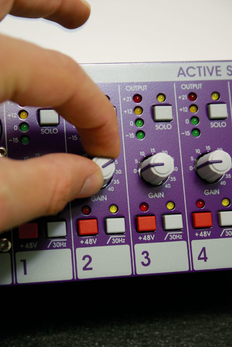
Hugh: We need to ensure that the gain in each stage of electronic processing within a signal path is optimised to keep the signal level well above the noise floor, but comfortably below the circuitry's clipping point. In a typical analogue microphonemixerrecorder chain, the first gain stage to adjust is the microphone preamp: adjust the gain so that the signal is brought up to a reasonable line level, with the biggest occasional transient peaks falling safely below the mixer's clipping point. Usually, you would achieve this by selecting the pre-fade level function on the channel and adjusting its input gain while looking at the signal level on the mixer's PFL meter. The meter display should hover around or a little below 0dB most of the time, with occasional higher peaks, but still comfortably below clipping level.
Paul: Keeping the signal level passing through each item of equipment as high as possible, while still leaving a little safety margin before clipping, is fairly easy to do with old-school analogue gear. The level meters usually have a safety margin of 10dB or more above the 0VU mark that can accommodate signal peaks, so if you aim to get your nominal signal level reading 0VU on the meters, you'll get good performance from the device. With digital circuits, there's no safety margin or area of progressive distortion above 0VU, as there is with analogue circuitry. As soon as you exceed 0VU you get clipping, so it's prudent to leave a safety margin of 12dB or so when setting levels. At the other end of the scale, a very small audio signal is represented by fewer bits, which translates into higher distortion levels, and this quantising distortion can sound very much like noise. Analogue noise is also added by all A-D converters, to some extent. However, if you're working with 24-bit audio, you can leave a 12dB safety margin without having to worry about noise.
Hugh: In many ways, the fact that the metering in digital systems shows the entire top half of the dynamic range is useful you can see exactly how high the transient peaks are reaching, and provided you keep them below 0dBFS, all will be well. On the other hand, the fact that a digital meter shows the entire headroom margin means that perfectly correct average levels will always look scarily low, hovering around the -30 to -20dBFS marks most of the time. This takes some getting used to, but it is worth it. Analogue systems provide 18-20dB of headroom above the nominal level for solid reasons, and 24-bit digital systems should emulate that.
Paul: Optimising gain structure where several bits of gear are connected together is even more demanding, as we need to ensure that every circuit is running at its optimum signal level, while still leaving the appropriate safety margin.
Hugh: Yes, and there are various places in the signal path where level can be changed, so we need to be aware of their effect on the overall signal level. For instance, if you apply a lot of EQ boost, the overall signal level will be increased. So although the microphone input stage has been adjusted to ensure the signal won't clip that part of the circuitry, the additional EQ gain could push the signal into clipping later in the signal path. Applying a lot of EQ boost is rarely a good idea, but if you need to it is worth reducing the mic preamp's gain to compensate. These basic principles apply for every other stage in the signal path where the level can be changed — faders, output levels, recorder input levels and so on. At every stage, think about where the signal level is in relation to clipping point and noise floor, and make adjustments to ensure that the noise level is acceptably low, while removing any risk of overload or clipping.
Paul: While a well-designed analogue mixer will have a sensible internal gain structure, you can run into problems when patching external hardware into insert points. You need to set the correct input levels to the connected device and also ensure that its output is at the correct level for the receiving device, in this case the console's insert return. Sometimes this can be as simple as setting the operating level of the external device to be the same as that of the console's insert points (usually -10dBV or +4dBu), but where the device itself has input and output level controls, you need to set these sensibly too, using any metering the device itself has to help you set the best level. If you find you're working with gain controls close to their maximum or minimum settings, you may have a problem. Also check that your peak signal level is roughly the same whether the external piece of gear is bypassed or not. The same applies when using aux sends to feed external effects; if you have your console send controls turned right down and compensate by turning the input gain of your external device right up, you're adding unnecessary noise.
Hugh: So, in practice, having the input and output gain controls somewhere in the middle of their travel is usually a good sign. The ideal when dealing with line-level signals is a unity gain situation where the signal stays at nominally the same level as it flows from device to device, rather than being constantly attenuated and then amplified, or vice versa.
Published October 2008
No comments:
Post a Comment