I have a vast amount of mic cable and a load of
three-pin Neutrik NC3FX female connectors ready for soldering (there is
no need for male connectors as the other ends are going to my patchbay).
I've done a limited amount of soldering in the past and just wondered
if there were any handy tips? I've got all the tools, including a
'desolderer' and a multi-clamp to hold things in place.
SOS Forum Post 
It always helps to tin any wires before soldering joints. Use a little solder on the twisted strands to lightly coat the wire.

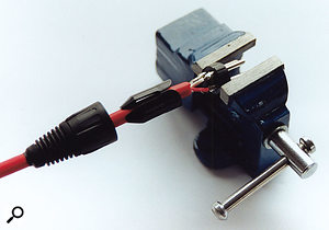
Make sure that your connector is securely fastened in a vice or clamp to stop any movement while you solder.

Leave any mistakes to cool before using a desolderer to clean the joint of any old solder, and then start again.
Technical Editor Hugh Robjohns replies: Wiring XLRs is one of the easier DIY challenges to tackle once you have a little experience under your belt. The solder contacts are large and fairly tolerant of over-heating, while cable trimming and dressing aren't too critical either. It's a good way for novices to get started and build their confidence in soldering and cable preparation.
The first step is to thread the cable through the strain-relief collar. It's immensely frustrating to have to unsolder a perfect connection just to put the collar back on, so don't forget! If you're planning to use slide-on cable identification markers, then put these on before the collar.
With the cable threaded through the collar, strip off the outer sheath and prepare the individual wires. It's best to use a proper wire stripper for this, and it's a good investment to buy the best self-adjusting type you can find. Using the wrong tool could damage the insulation and/or nick the wires. The former risks short circuits, the latter risks breakages and open circuits.
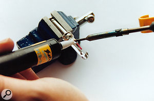
With the wires trimmed to an appropriate length and stripped, it helps to 'tin' them. Twist the strands tightly together, heat each wire, and feed in a little solder so that it flows and coats the metal. Don't get it too hot, though, as the insulation is likely to melt or shrink.
It's good practice to then introduce some insulation sleeving over the screen wire, to prevent short circuits inside the connector body. You can buy bags of pre-cut rubber sleeves that make the job neat and tidy, and they also allow for easy re-working if you need to repair the connection at a later stage. Heat-shrink sleeving can be used, but makes the job of repairs slightly more difficult. Also, at this stage, decide which of the two core wires will be denoted as 'hot' and which as 'cold' — make a decision and stick to it!
Next, fix the connector into a small vice or multi-clamp in such a way that allows you to access the three pins, and then tin each of them. If you don't have a vice or clamp, then you could use a cable tester, or a similar device (the heavier the better to stop things moving around too much while you are working), as long as the connectors are fitted somewhere convenient. Also, I find it helps to point the female end of the connector slightly uphill, otherwise the solder disappears inside the terminal!
Identify the pin numbers (these are usually embossed beside each pin on both the inside and outside of the connector) and remember that the male and female connectors are mirror images of each other. For that reason, it makes sense to wire all the connectors of one sex first, and then all those of the opposite sex. If you alternate between wiring male and female connectors, it is inevitable that you will end up wiring at least one backwards!
Once you have correctly identified each pin, offer the 'cold' wire from the cable to pin 3 (it's the the one in the middle). Hold it steadily in place while you heat both the wire and the terminal, and then feed in some solder. As soon as the solder melts, remove the heat and hold everything still until it cools and the solder sets — it should be just a few seconds.
The key is to be be as quick, clean and precise as possible. Don't keep jabbing at the solder joint. If it isn't right, do the next joint and come back to any problem later once it has cooled. Use the solder-sucker (desolderer) to clean the joint of any old solder and start again.
Repeat the process for the 'hot' wire on pin 2, and then the screen wire on pin 1. I don't recommend linking pin 1 to the connector shell as it usually causes more trouble than it's worth, but there is a central tag for that purpose if you should require it.
If you're happy with the solder joints, fit the plastic insulation and cable clamp sleeve. Slide the whole thing into the metal shell (being careful to align the rib and notch), ease the release button into place and screw the end-gland up tight. Always test the cable to make sure that it's wired correctly (with particular attention to pin 1/pin 3 reversals). In the case of patchbay wiring, it pays dividends to label the cable ends in some meaningful manner, making it easier to replug things later.
Published June 2008
No comments:
Post a Comment